Active Elements and Passive Elements :-
We can classify the Network elements into either active or passive based on the ability of delivering power.
● Active Elements deliver power to other elements, which are present in an electric circuit.Sometimes, they may absorb the power like passive elements. That means active elements have the capability of both delivering and absorbing power.
Examples: Voltage sources and current sources.
●Passive Elements can’t deliver power (energy) to other elements, however they can absorb power.That means these elements either dissipate power in the form of heat or store energy in the form of either magnetic field or electric field.
Examples: Resistors, Inductors, and capacitors.
Linear Elements and Non-Linear Elements
We can classify the network elements as linear or non-linear based on their characteristic to obey the property of linearity.
●Linear Elements are the elements that show a linear relationship between voltage and current.
Examples: Resistors, Inductors, and capacitors.
● Non-Linear Elements are those that do not show a linear relation between voltage and current.
Examples: Voltage sources and current sources.
Bilateral Elements and Unilateral Elements Network elements can also be classified as either bilateral or unilateral based on the direction of current flows through the network elements. Bilateral Elements are the elements that allow the current in both directions and offer the same impedance in either direction of current flow.
Examples: Resistors, Inductors and capacitors.
The concept of Bilateral elements is illustrated in the following figures.

In the above figure, the current (I) is flowing from terminals A to B through a passive element having impedance of Z Ω. It is the ratio of voltage (V) across that element between terminals A & B and current (I).
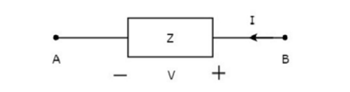
In the above figure, the current (I) is flowing from terminals B to A through a passive element having impedance of Z Ω. That means the current (–I) is flowing from terminals A to B. In this case too, we will get the same impedance value, since both the current and voltage having negative signs with respect to terminals A & B.
Unilateral Elements are those that allow the current in only one direction. Hence, they offer different impedances in both directions. We discussed the types of network elements in the previous chapter. Now, let us identify the nature of network elements from the V-I characteristics given in the following examples.
Example 1
The V-I characteristics of a network element is shown below.

Step 1 − Verifying the network element as linear or non-linear.
From the above figure, the V-I characteristics of a network element is a straight line passing through the origin. Hence, it is linear element.
Step 2 − Verifying the network element as active or passive.
The given V-I characteristics of a network element lies in the first and third quadrants.
● In the first quadrant, the values of both voltage (V) and current (I) are positive. So, the ratios of voltage (V) and current (I) gives positive impedance values.
● Similarly, in the third quadrant, the values of both voltage (V) and current (I) have negative values. So, the ratios of voltage (V) and current (I) produce positive impedance values.
Since, the given V-I characteristics offer positive impedance values, the network element is a Passive element.
Step 3 − Verifying the network element as bilateral or unilateral.For every point (I, V) on the characteristics, there exists a corresponding point (-I, -V) on the given characteristics. Hence, the network element is a Bilateral element. Therefore, the given V-I characteristics show that the network element is a Linear, Passive, and Bilateral element.
Example 2
The V-I characteristics of a network element is shown below.

Step 1 − Verifying the network element as linear or non-linear.
From the above figure, the V-I characteristics of a network element is a straight line only between the points (-3A, -3V) and (5A, 5V). Beyond these points, the V-I characteristics are not following the linear relation. Hence, it is a Non-linear element.
Step 2 − Verifying the network element as active or passive.
The given V-I characteristics of a network element lies in the first and third quadrants. In these two quadrants, the ratios of voltage (V) and current (I) produce positive impedance values. Hence, the network element is a Passive element.
Step 3 − Verifying the network element as bilateral or unilateral.Consider the point (5A, 5V) on the characteristics. The corresponding point (-5A, -3V) exists on the given
characteristics instead of (-5A, -5V). Hence, the network element is a Unilateral element.Therefore, the given V-I characteristics show that the network element is a Non-linear, Passive, and Unilateral element. The circuits containing them are called unilateral circuits.
Lumped and Distributed Elements
Lumped elements are those elements which are very small in size & in which simultaneous actions takes place. Typical lumped elements are capacitors, resistors, inductors.
Distributed elements are those which are not electrically separable for analytical purposes.For example a transmission line has distributed parameters along its length and may extend for hundreds of miles.
Tags:
electrical
